
Recent Blog Posts

Fab Academy Final Project
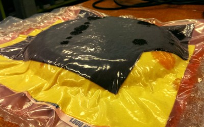
For Fab Academy we were required to complete a final project that incorporated many of the skills we had learned throughout the course. Inspired by a friend who had a radio in his bathroom that was always in and tuned to a jazz station. For my final project I decided to create a small bathroom radio that would turn on when you entered turn off when you left and have a few other fancy features. This page documents that project: Project Name: pJazz What will it do? * Play jazz music from a local FM station when you enter the bathroom. * Turn on based on input from a PIR sensor. * Turn off when you leave. * Display info on a small OLED display. * Diaplay RBDS info about the music if it’s being broadcast on the signal. * Display the current time (As the RBDS encodes this so why not) * Provide hands free interfacing with capacative touch proximity sensing Who’s done what beforehand? Here is a hack where someone wired a small portable mp3 player into their bathroom light on the ceiling. Example of interfacing a similar FM receiver chip with an Arduino. Arduino Shield with similar chip on board FM receiver chip. Designs for laser cut speaker enclosures are quite abundant. What materials and components will be required and where will they come from? Enclosure Acrylic or Wood (Fab Lab) Speaker (Junk Drawer) OLED display (Adafruit) PIR sensor(Amazon) Battery (Adafruit) Circuit Boards (Fab Lab) Main control unit ATMega328 FM receiver SI4705 Amplifier (adafruit) TPA2016 module Power/Battery Charger MCP73831T Touch sensor pads Aditional components for all circuit boards (Mouser) What will...Read moreWe recognize that private ownership over media, ideas, and technology is rooted in European conceptions of property and the history of colonialism from which they formed.
Fab Academy E15: License and Intellectual Property
Licensing of my Final Project My final project will be using the Decolonial Media License 0.1 It’s a Share Alike + Attribution license very similar to the Free Art License 1.3, GNU Free Documentation License 1.3, or Creative Commons Attribution-ShareAlike 4.0 International License. Why? Well I think the wording from the license describes it best: We recognize that private ownership over media, ideas, and technology is rooted in European conceptions of property and the history of colonialism from which they formed. These systems of privatization and monopolization, namely copyright and patent law, enforce the systems of punishment and reward which benefit a privileged minority at the cost of others’ creative expression, political discourse, and cultural survival. The private and public institutions, legal frameworks, and social values which uphold these systems are inseparable from broader forms of oppression. Indigenous people, people of color, queer people, trans people, and women are particularly exploited for their creative and cultural resources while hardly receiving any of the personal gains or legal protections for their work. We also recognize that the public domain has jointly functioned to compliment the private, as works in the public domain may be appropriated for use in proprietary works. Therefore, we use copyleft not only to circumvent the monopoly granted by copyright, but also to protect against that appropriation. Dissemination The current plan is to leave pJazz in by bathroom and then guests can experience it for themselves. My backup plan would be to create a super cheap version that could be left is restrooms thus providing music for restooom users at completely random...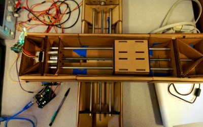
Fab Academy E14: Machine Design
Designing Network Controllable Stepper Motor Nodes For machine building week our group decided to try and create a 2-axis machine with a stage that could track the motion of a pen drawing on a tabled. My part of the project was to design networked arduino nodes that could be individually addressed and receive synchronization commands. I2C and Arduino We chose to use an I2C network for communicating between the Arduino nodes. The I2C standard includes allows for communicating with each node through unique addresses assigned to the nodes. It also provides support for a General Call address (specifically 0x00) that all nodes will respond to. The problem here is that by default the Arduino I2C library does on enable the General Call response feature. Enabling the General Call response in Arduino The ATmega has built in support for the I2C standard but it’s referred to as it’s Two Wire Interface in all of the documentation. In order to enable the General Call address we only need to add this one line of code in our setup function: TWAR = 0x03; Now is we send out a data on the I2C bus with a destination address of 0x00 all devices on the bus will receive the message. Node Protocol Each node can receive two types of commands. Either a setup move which consists of 6 bytes that define the number of steps, step direction, and speed of the move. The second possible command is synchronized move command that all nodes receive and initiated the start of a movement. Here is the code for an individual node: // Arduino based networked...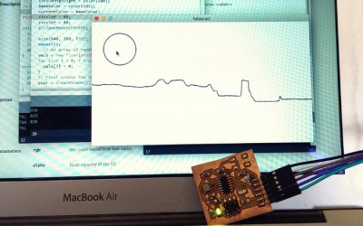
Fab Academy E13: Interface and Application Programming
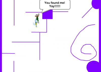
Processing I chose to use processing this week as I had never used it before and am curious about it’s similarities to the Arduino IDE. Much like with most Arduino projects I started by playing with a few example sketches. I ended up hacking together parts from the built in serial SimpleRead example and this example for plotting a graph. With those two I was able to get a simple live graph running that would display light levels from my board over time once the arduino was set up. Arduino Setup I setup my input/output board to continuously read light levels from the phototransistor and send the reading out on the serial port. I also programmed it to listen to the serial port and turn on the boards led on or of depending it a ‘1’ or ‘0’ is received on the serial port input. (The full code is at the end of this post) void loop() { lightValue = analogRead(sensorLight); mySerial.println(lightValue); if (mySerial.available()) { // If data is available to read, val = mySerial.read(); // read it and store it in val } if (val == '1') { // If 1 was received digitalWrite(ledPin, HIGH); // turn the LED on } else { digitalWrite(ledPin, LOW); // otherwise turn it off } delay(30); // Wait 30 milliseconds for next reading } And then used parts of this example for adding in a button that could trigger the sending of a ‘1’ or ‘0’ to the board. (The full code is at the end of this post.) At this point I had a funtioning GUI that could display input from the board...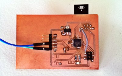
Fab Academy E12: Networking and Communications
The Plan This week I wanted to wirelessly network multiple microcontroller boards using the super cheap nRF24L01+ modules. Breadboarding The internet warned me that they can be quite flaky and tricky to use with the ATtiny44 so I decided to breadboard a few with an Arduiono UNO and Trinket(ATtiny85) as a starting point. I had to install a custom library for using the Trinket(ATtiny85). Also it’s very important to follow all the warning about adding an extra 10uF capacitor between GND and VCC on the RF module. I had lots of problems until I decided to follow that advice. ATtiny time I then created and ATtiny board thinking that it would be east to port the code from the ATtiny85 to the ATtiny44. This was not the case. The ATtiny couldn’t use the same library and lot of the documentation on it indicated the ATtiny44 wasn’t fully tested with the library. Also the 4k of memory in the ATtiny wasn’t nearly enough to do both the networking functions and anything else interesting. ATmega time Next it was time for an ATmega board. This was also tricky because I started with an ATmega88 which it turns out isn’t supported by the Arduino IDE. I then killed a board attempting to switch it out for an ATmega328. However this board did finally work. It works! I programmed the boards so that one can be a remote control for the other. When you press the button on the remote board it sends a signal to toggle the LED on the other board. Video of it working Design Files The Eagle CAD design files can...