by Jeffrey Putney | Mar 16, 2015 | Fab Academy
Datasheets and Software Serial This week I read through the ATtiny summary datasheet. The main thing I learned is why the standard serial communication library can’t be used with the ATtiny44. Looking at the Arduino Serial library I saw that it mentions it uses a chip’s UART for communication. But our ATtiny’s apparently don’t have UARTs. As you can see if you search the ATtiny summary datasheet you won’t find a UART. Luckily the SoftwareSerial library has been written which implements the UART functionality in software and that library has been bundled into the Arduino environment. The Datasheet also mentioned the QTouch library which I would like to learn more about in the future. This weeks project This week the plan is to create a microcontroller board that provides 2 way communication with the serial port on the computer. I started testing by opening the Examples->SoftwareSerial->SoftwareSerialExample in the Arduino software. At first this refused to compile for the ATtiny44. I realized from the code comments that this example file was attempting to also use the hardware serial port: //Receives from the hardware serial, sends to software serial. //Receives from software serial, sends to hardware serial. So I went through and removed all the references to the Hardware Serial connection, which look like this: Serial.begin(4800); //Start Hardware Serial Connection Instead of this: mySerial.begin(4800); //Start Software Serial Copnnection In other words we only want to work with the `mySerial` object, and not the `Serial` class. 2-way Serial Communication Code #include <SoftwareSerial.h> SoftwareSerial mySerial(0, 1); // RX, TX const int buttonPin = 2; int led = 7; int incomingByte = 0; // for...

by Jeffrey Putney | Mar 10, 2015 | Fab Academy
Motivation For my final project I need a solar collection system that can charge a battery in bright indoor condition. So for this weeks assignment I chose to design a circuit and subsequent board based on the TI BQ2505 Ultra Low Power Energy Harvester Chip and a 5V boost converter chip to so that this version can at least charge a cell phone. Circuit Design The first step was following the reference designs from the data sheets and creating a schematic in eagle. The trickiest part here was choosing all the resistor values to set the battery charge values and hysteresis points. Board Layout This took some time and iterations with trying to mill the boards. The only packages available for the two chips where no lead packages that required traces that only the .010 inch mill bit could mill out. To increase the chance that traces would survive milling I had to create copper pour sections that widened as soon as they left the chips pad areas. Milling I lost a few .010 bits before I realized the set screw was too striped and no longer tightning far enough Reflow Soldering This actually went pretty smooth. surface tention managed to seperate the almost all the solder between the smallent surace mount pins though a few had the be reflowed after with a fine tip soldering iron in order to get them to seperate. It worked!!!! Even under desk lamp lighting the circuit was able to power up and provide a charge current for the Li-po battery. The boost converter was also able to start up and provide a...

by Jeffrey Putney | Mar 7, 2015 | Fab Academy
Scanning For scanning this week I used an XBox Kinect and the ReconstructMe software package. The scan process was as simple as starting the script and rotating slowly while I stood in front of the Kinect. I then fixed a few holes and cleaned up the bottom edges with netfab Basic. To make sure eveything the final model was in good shape I opened it in Tinkercad and checked that I had some humanoidish object like looked a little like me. STL file of the scan can be downloaded here. 3D Printing The goal for 3D printing this week was to create something that couldn’t easily be made by a subtractive fabrication technique. So I chose to remix this Math Gyro Maker part that provided a good template for interlocking rotational joints. I modified the outer and inner ring to recreate the logo from the Heartland Maker Fest event I help organize. Here’s the first print from our Up Mini 3D Printer printing with ABS plastic: The rotational joints were a bit loose and could have been made with tighter tolerances, but they worked perfectly. And it’s a necklace! The final STL file can be downloaded...

by Jeffrey Putney | Feb 24, 2015 | Fab Academy
This week the goal was to created and populated FabISP boards. I followed the instructions provided here. The only change I made was to edit the original design slightly so use an oscillator instead of a crystal. I Also added a hedgehog to the board to make it clear which FabISP was mine. Next I cut the board on the Roland Modela. I then used the the tCream layer from Eagle cad as a template for a solder mask I created on the vinyle cutter. This allowed me to nicely screen print solder paste onto the board. Then it was time for the oven. I plugged in the board and it passed the smoke test. I was then able to use Crosspack and Xcode to program the progremmer with another programmer. Once programmed the extra solder bridge and resistor was removed and the board was ready for...
by Jeffrey Putney | Feb 18, 2015 | Fab Academy
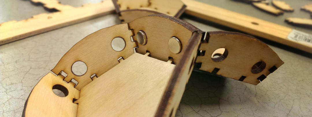
Assignments for the week: Use a computer controlled cutting tool to make a pressfit objects can that can build into larger objects. Learn how to design pressfit objects that account for the physical realities of fitting them together. Violate a patent. (well this became a personal goal once I realized that what I wanted to make would in fact violate one ) So let’s violate a patent. It’s easy! A few weeks ago a friend showed me a bunch of small parts he 3D printed that would assemble into a polyhedron when you put a bunch of them in a box and shake them up. Aparently he had found the design on Thingiverse, printed his own copy, and then shared a picture of it back on thingiverse. He then got a message that said what he created most likely violated this patent, which basically claims that only one person in the US has the right to make a polyhedra that snaps together in only one way using magnets. The message also said that if he was only printing it for educational purposes he was probably safe from legal attack. Then the entire model page went missing from the thingiverse. So I decided to recreate a new pressfit version this week. First the sketch I started by modeling a single side in blender. I then used the the UV Unwraping function to create a cut pattern for each side. Blender allows you to save a high resolution bitmap of the side which I then opened up in Illustrator to create a final vectorized version for cutting. Here is the Blender File. Time to...